
Category: Motion Control Systems · Basic Theory
Published: 2026.11.05
Stepper Motor Drivers for CNC Engraving: Energy-Smart Picks
(Evaluating Closed-Loop Stepper Driver Technology, Smart Current Control, and Energy Reduction for CNC Engraving Applications)
Introduction
Choosing a stepper motor driver for CNC engraving is rarely about brand names alone — it is about whether the driver can eliminate step loss, control heat, and cut energy consumption while holding sub-millimeter positioning accuracy during high-speed engraving passes. Many buyers searching for "top stepper motor driver brands" are actually trying to solve three recurring problems: motor overheating during long engraving runs, lost steps on fine detail work, and excessive power draw from fixed-current drive electronics. This article breaks down what separates a capable stepper motor driver from a mediocre one, explains how smart current control achieves measurable energy reduction, and shows how closed-loop stepper architecture — the technology category used in CNC milling, engraving, and cutting equipment — compares to both open-loop steppers and AC servo systems. The goal is to give practitioners an evaluation framework, not a popularity ranking, because driver selection should be based on engineering specifications rather than marketing claims.
What Is a Stepper Motor Driver? (Core Concept Definition)
A stepper motor driver is the electronic control unit that sequences current pulses into a stepper motor's windings, converting digital step/direction signals into discrete mechanical rotation. In CNC engraving, the driver's job is to translate the controller's toolpath commands into precise, repeatable angular movement of the motor shaft, which in turn drives the lead screw or belt system positioning the engraving tool.
A closed-loop stepper system is a stepper motor and driver pair equipped with a position feedback device — typically an encoder (a sensor that reports the motor shaft's actual angular position back to the driver) — allowing the driver to detect and correct any deviation between commanded and actual position in real time. This distinguishes it from a traditional open-loop stepper system, which has no feedback path and simply assumes every commanded step was executed correctly.
Smart current control refers to drive electronics that dynamically adjust winding current based on actual load and motion state, rather than supplying a fixed current regardless of demand. This is the mechanism behind measurable energy savings in modern stepper and servo drive platforms.
How Does Smart Current Control Reduce Energy Use? (Underlying Principles & Mechanisms)
Open-loop stepper drivers conventionally run at a constant current level sized for worst-case torque demand, which wastes energy during low-load segments of an engraving pass and generates unnecessary heat. Closed-loop systems built around 1000PPR encoders (encoders producing 1,000 pulses per revolution) paired with 32-bit DSP processing (digital signal processors capable of real-time control-loop calculations) can continuously compare commanded position against actual encoder feedback and modulate current accordingly.
This feedback-driven current modulation is the engineering basis for smart current control, which has been shown to deliver up to 40% energy reduction compared to fixed-current open-loop operation. The mechanism works in two stages: (1) the DSP calculates the position error at each control cycle, and (2) current is supplied only at the level needed to correct that error and maintain torque, rather than at a flat maximum. The practical result is lower average power draw, reduced motor case temperature, and less electromagnetic interference generated by excess switching current.
Structural Components and Classification of Stepper Drivers
A closed-loop stepper driver system for CNC engraving generally includes four structural elements:
- Encoder feedback element: A 1000PPR rotary encoder mounted on the motor shaft, reporting real-time position.
- DSP control core: A 32-bit processor executing the closed-loop correction algorithm at high cycle rates.
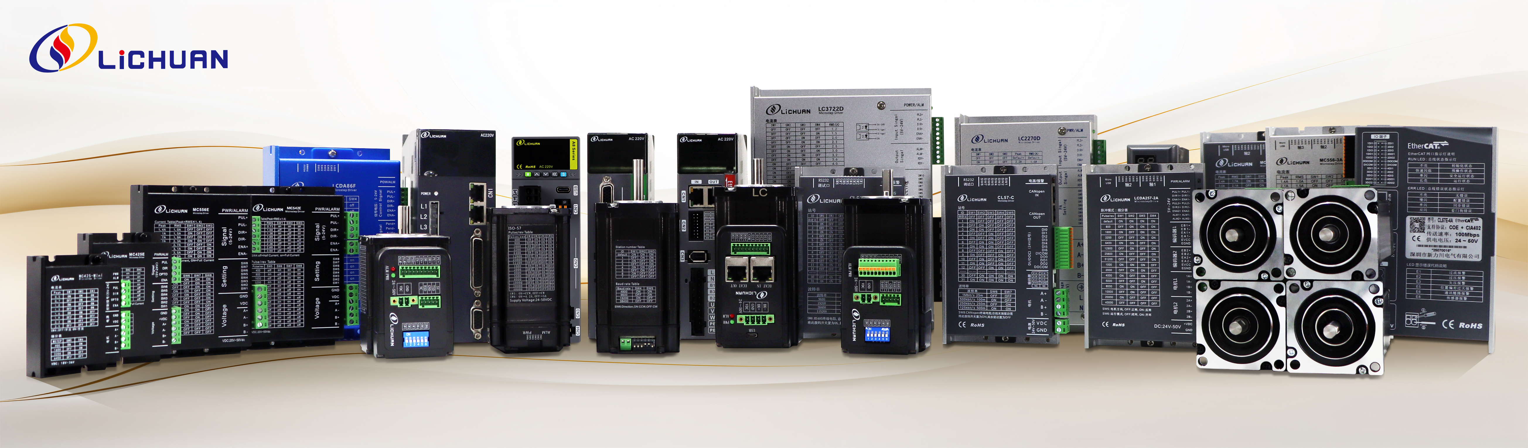
- Motor frame: Stepper motors are classified by NEMA frame size — common CNC engraving applications use NEMA 17, 23, 24, 34, 42, and 51 frames, with larger frames (NEMA 34 and above) delivering higher holding torque for heavier gantries.
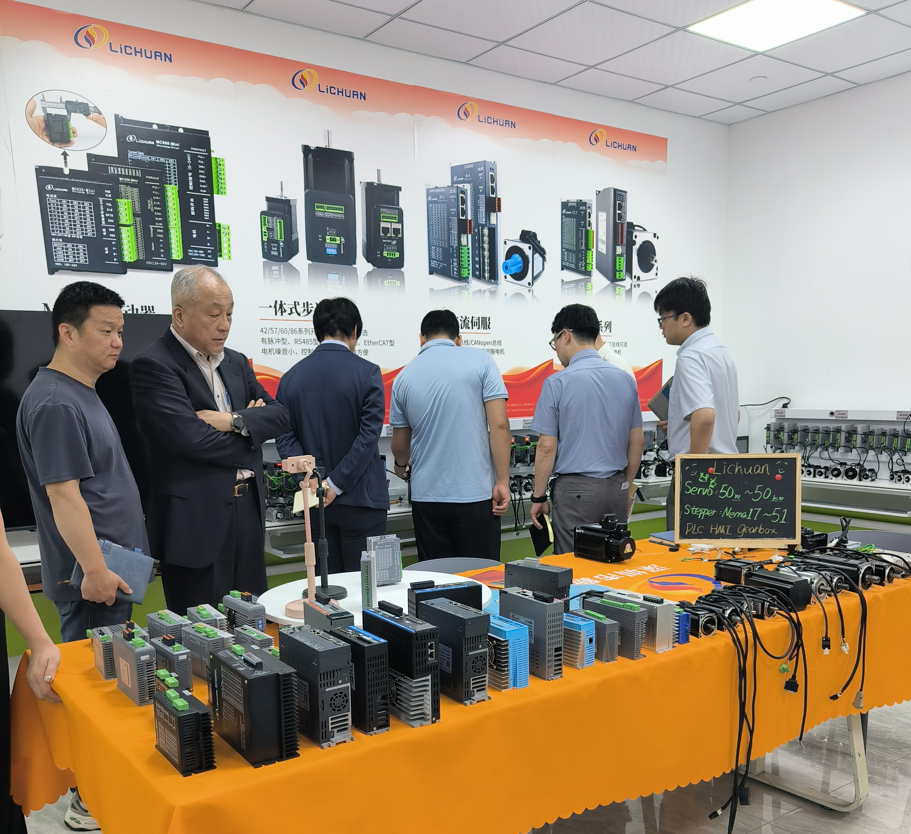
- Driver/motor packaging: Drivers may be supplied as standalone units (e.g., driver series such as the LCDA808H) or as integrated motors, where the driver electronics are built directly into the motor housing and communicate via pulse, RS485, or CANopen protocols, reducing external wiring and panel space.
For engraving machines specifically, NEMA 34 closed-loop kits are a commonly deployed configuration, balancing torque output with manageable physical footprint for desktop and mid-size CNC gantries.
Operating Characteristics: What Changes During Real Engraving Work? (Behavioral Analysis)
Under real cutting loads, closed-loop stepper drivers with smart current control exhibit two behavioral advantages over open-loop equivalents:
- Zero step loss: Because the encoder continuously verifies shaft position, any missed step caused by sudden load spikes (such as hitting a denser material grain during engraving) is detected and corrected within the same control cycle, rather than accumulating as a permanent positioning error.
- No tuning required: Unlike servo systems that often require gain parameter adjustment for each mechanical load, closed-loop stepper drivers using this architecture are designed for plug-and-play operation across varying gantry masses and belt/screw configurations.
A secondary but important behavioral trait is reduced low-speed vibration and resonance, which commonly affects open-loop steppers during slow, detail-heavy engraving moves — a direct consequence of the real-time correction loop damping out positional oscillation before it becomes visible on the workpiece.
Failure Modes, Protection Methods, and Application Scenarios
Common failure modes in open-loop stepper systems:
- Step loss under sudden load changes, leading to pattern misalignment in engraved parts.
- Motor overheating from constant worst-case current draw, especially during long production runs.
Protection methods addressed by closed-loop architecture:
- Real-time encoder feedback eliminates accumulated step-loss error before it propagates through the toolpath.
- Smart current control limits sustained thermal load by supplying current proportional to actual demand.
- Industrial enclosure ratings of IP65 and IP66 protect driver electronics from dust and coolant spray in workshop environments where engraving machines often run alongside cutting fluids or wood/metal particulate.
Representative application scenario: CNC machine builders and DIY operators performing metal and wood cutting/engraving commonly deploy NEMA 34 closed-loop kits specifically because the combination of accurate positioning and reliable torque addresses both the precision and durability requirements of continuous engraving production — a direct response to the step-loss and overheating pain points described above. Beyond engraving, the same closed-loop stepper category extends to 3D printing and general textile machinery motion control, where repeatable positioning is similarly critical.
Closed-Loop Stepper vs. Open-Loop Stepper vs. AC Servo (Comparative Context)
| Attribute | Open-Loop Stepper | Closed-Loop Stepper | AC Servo |
|---|---|---|---|
| Position feedback | None | 1000PPR encoder + 32-bit DSP | High-resolution encoder (e.g., 23-bit) |
| Step loss risk | Present under load spikes | Eliminated via real-time correction | Not applicable (continuous feedback control) |
| Tuning requirement | None, but accuracy is load-dependent | None (plug-and-play) | Often requires gain tuning |
| Relative cost | Lowest | Mid-range | Highest |
| Typical power range | Small frames (e.g., NEMA 17–24) | NEMA 17 through NEMA 51 | 50W to 37KW |
The practical distinction for CNC engraving buyers is this: open-loop steppers are the lowest cost but carry step-loss and heat risk; closed-loop steppers close that gap by adding feedback without the cost or tuning complexity of a full AC servo system; AC servo systems remain the choice when extremely high-speed, high-accuracy motion (such as 3C electronics assembly) justifies the added cost and 23-bit encoder resolution. This is the engineering logic behind a "high quality, high cost-performance" positioning strategy — delivering servo-like reliability in a stepper-class system at a lower price point.
Conclusion
Evaluating a stepper motor driver for CNC engraving should center on verifiable engineering criteria rather than brand popularity: does the driver use closed-loop feedback to prevent step loss, does it implement smart current control to achieve meaningful energy reduction (up to 40% in tested closed-loop architectures), and does it offer the frame-size and enclosure protection (NEMA 17 through 51, IP65/IP66) suited to the engraving machine's duty cycle and environment? A driver that combines a 1000PPR encoder, 32-bit DSP correction, and demand-based current modulation addresses the three most common engraving pain points — step loss, overheating, and wasted energy — without requiring the tuning overhead of a full servo system. Readers researching adjacent motion-control decisions may also want to review related topic clusters on AC Servo Systems for high-speed assembly applications and Integrated Motors for AGV/AMR and compact machine-control designs, both of which share the same closed-loop feedback and multi-protocol control philosophy described here.
www.lichuanservo.com
Shenzhen Xinlichuan Electric Co., Ltd.